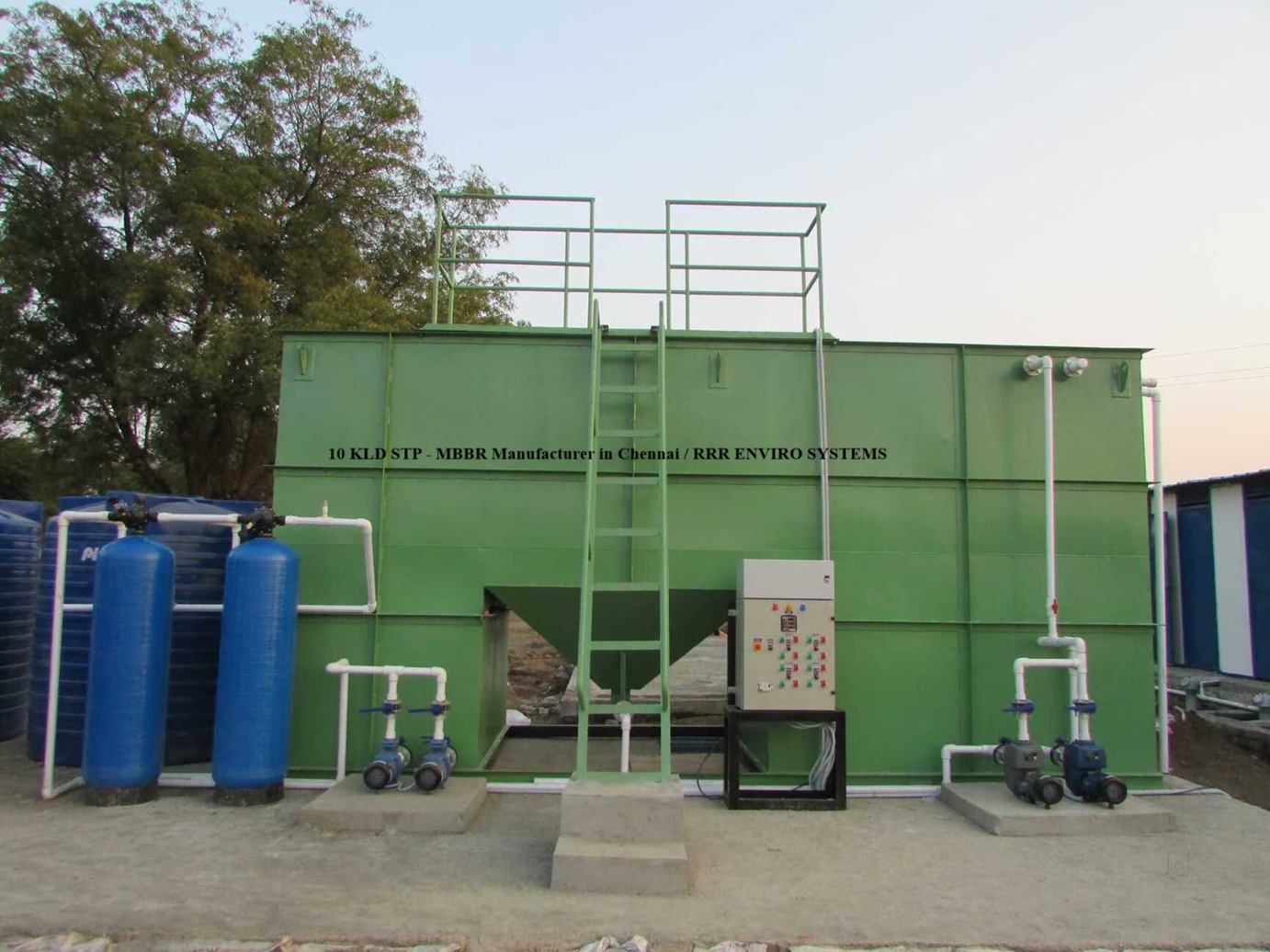
30 KLD Sewage Treatment Plant — MBR (Membrane Bioreactor)
Quick Summary
Design capacity: 30 KLD (30 m³/day). Technology: Membrane Bioreactor (Submerged MBR). Default design basis used: 20 operating hours/day, conservative assumptions for influent BOD = 250 mg/L. Final design & guarantees after receiving site influent data.
Process Flow (Text Diagram)
MBR removes the need for a separate secondary clarifier — membranes provide solid–liquid separation, enabling compact design and high-quality permeate suitable for reuse following disinfection/polishing.
Design Basis & Digit-by-Digit Calculations
- Daily flow Qday = 30.000 m³/day
- Operating hours = 20 hr/day
- Hourly flow Qhr = Qday ÷ 20 = 1.500 m³/hr
- Assumed influent BOD₅ = 250 mg/L (adjust after lab report)
- MBR membrane design flux (conservative submerged) = 10 LMH (litres/m²·hr)
1) Convert flows (digit by digit)
2) Membrane area (permeate flux method)
If a typical submerged membrane module (vendor dependent) has active area ≈ 10 m²/module → modules ≈ 150 ÷ 10 = 15 modules. (Module area varies by vendor — final module count after vendor selection.)
3) Biological reactor volume (MLSS & HRT)
Assume MLSS (mixed liquor) = 8,000 mg/L (8.0 kg/m³) for MBR (MBRs operate at higher MLSS than conventional ASP). Biomass mass = MLSS × V = 8.0 × 6.000 = 48.0 kg solids in reactor.
High MLSS reduces reactor volume required; membrane scouring & mixing must be provided to avoid membrane fouling and to maintain biofilm health.
4) BOD load & oxygen demand
Oxygen demand (assume 1.4 kg O₂/kg BOD removed) = 7.5 × 1.4 = 10.5 kg O₂/day.
Convert to blower size using conservative 1.2 kg O₂/kW → blower power ≈ 10.5 ÷ 1.2 = 8.75 kW ≈ choose 9 kW. Additionally, membrane scouring air (intermittent) is required — assume 20% extra capacity for scouring & mixing → total blower capacity ≈ 8.75 × 1.20 = 10.5 kW → choose a 11 kW blower (duty + standby recommended).
Final blower selection must use vendor OTR data and site temperature. Provide VFDs for blower control and fine DO regulation.
5) Sludge production (estimate)
All calculations above are working estimates — final design will be refined after receiving the actual influent lab report (BOD, COD, TSS, FOG, TDS, pH) and site constraints.
Membrane Modules & Layout
- Submerged hollow-fiber or flat-sheet modules (vendor dependent). Estimated total area ≈ 150 m² (for 10 LMH flux assumption).
- Typical module area (example) ≈ 8–12 m²/module → indicative modules ≈ 12–19 modules (select after vendor datasheet).
- Mount modules in racks/frames with permeate headers and manholes for access. Provide spare modules & cleaning protocol.
- Include in-situ chemical cleaning (CIP) connections: NaOH & acid dosing, backwash / relaxation cycles as per vendor recommendations.
Scope of Supply & Equipment
- Screening & grit / oil-grease trap
- Equalization tank with mixer & level control
- Bioreactor tank with submerged membrane modules (MBR tank)
- Submerged membrane modules + racks + permeate headers
- Blowers (11 kW duty + standby) with air manifolds and scouring control
- Permeate pumps, recirculation pumps, chemical dosing pumps (cleaning & disinfection)
- Permeate polishing: UV / Hypo dosing and sand/cartridge filters as required
- Sludge sump, thickening & dewatering arrangement (drying beds or mechanical)
- PLC control panel with membrane run/relax schedule, DO control, level sensors & alarms
- Piping, valves (SS/UPVC), instrumentation, civil anchors, installation & commissioning
Expected Performance & Applications
| Parameter | Typical Influent | Expected Permeate / Effluent |
|---|---|---|
| BOD₅ | 200 – 400 mg/L | < 10 – 30 mg/L (MBR permeate often < 10–20 mg/L depending on operation) |
| TSS | 150 – 350 mg/L | < 5 – 10 mg/L (MBR gives very low TSS) |
| COD | 600 – 1200 mg/L | < 150 – 300 mg/L (site dependent) |
| Turbidity | Varies | < 1 NTU (excellent clarity) |
| Use | — | Toilet flushing, landscaping, cooling tower makeup (after disinfection / polishing) or further RO if needed |
MBR provides near-membrane quality effluent — suitable for many reuse applications, reducing the need for large polishing units and clarifiers.
Operation & Maintenance
- Daily: check membrane permeate flux, transmembrane pressure (TMP), permeate quality (TSS/Turbidity), blower & pump status.
- Weekly: verify scouring schedule, inspect header & manifold, top-up chemical stocks for CIP.
- Monthly: chemical cleaning as per vendor (CIP cycles), check membrane integrity, calibrate sensors.
- Periodic: replace pre-filters, backwash if applicable, schedule membrane replacement plan (membrane life typically several years depending on feed & maintenance).
- Provide operator training, spare parts list and AMC options for long-term performance.
FAQ — 30 KLD MBR STP
Q1: What are the advantages of MBR over conventional STP?
MBR gives a much smaller footprint, superior solids separation (very low TSS), better effluent quality suitable for reuse, and lower sludge production. It's ideal where land is limited or reuse standards are strict.
Q2: What membrane maintenance is required?
Periodic chemical cleaning (CIP), monitoring TMP and flux, and occasional physical inspection. Proper pre-treatment and scouring air reduce fouling and extend membrane life.
Q3: Do you provide commissioning and AMC?
Yes — we provide full commissioning, start-up assistance, operator training and AMC packages across India.
Q4: What raw data is needed to finalize design?
Please share raw influent lab report: BOD, COD, TSS, FOG, pH, temperature, any industrial contaminants. We offer free jar tests & on-site analysis for serious enquiries.