3000 LPH Iron Removal Plant (3.0 m³/hr)
Quick Summary
Design flow: 3,000 LPH = 3.0 m³/hr (72.0 m³/day).
Typical feed: Borewell / Groundwater with iron (Fe) & manganese (Mn) contamination.
Process: Aeration / chemical oxidation → Settling / React tank → Pressure multimedia filter (sand/anthracite or manganese greensand) → Polishing (ACF / cartridge / UV if required).
Process Flow (text)
Disinfection and remineralization added if water is used for potable supply. We design according to site raw water chemistry and local regs.
Digit-by-Digit Design Calculations (24 hr operation assumed)
- Plant flow = 3,000 LPH (3.0 m³/hr)
- Operating hours = 24 hr/day → daily volume = 3.0 × 24 = 72.0 m³/day
- Design oxidation contact time = 15 minutes (0.25 hr) — typical starting point for Fe oxidation
- Filter design face velocity = 6 m/hr (typical for pressure media filters)
- Filter bed depth (effective) = 0.8 m (800 mm) for manganese-sand or layered media
Step 1 — Convert flows
Convert to m³/hr: 3,000 ÷ 1000 = 3.0 m³/hr.
Daily volume = 3.0 × 24 = 72.0 m³/day = 72,000 L/day.
Step 2 — Iron mass to remove (examples)
Step 3 — Oxidation / contact tank sizing
Required reactor volume V = Qhr × contact_time = 3.0 × 0.25 = 0.75 m³ (750 L). Add freeboard (20%) → physical tank ≈ 0.75 × 1.20 = 0.90 m³ (900 L).
Step 4 — Filter area & vessel diameter (face velocity method)
Required filter bed area A = Qhr ÷ velocity = 3.0 ÷ 6 = 0.50 m².
Convert area to circular vessel diameter d: d = √(4·A / π) = √(2 / π) ≈ √(0.6366197) ≈ 0.80 m → choose vessel diameter ≈ 800 mm (practical size: 0.8–1.0 m dia).
Step 5 — Media volume (bed depth method)
Step 6 — Backwash rate estimate
Backwash flow Q_bw = area × backwash_velocity = 0.50 × 20 = 10.0 m³/hr = 10,000 L/hr = 166.7 L/min. Provide backwash source (raw water booster) or recycle backwash tank with pump.
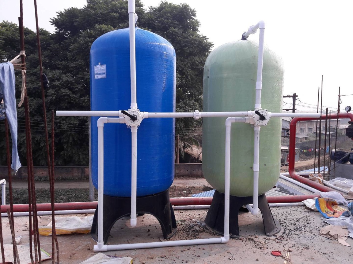
Design interpretation: The single-vessel design (0.8 m dia × bed depth 0.8 m, media ≈ 400 L) suits the full flow; however, for continuous supply during regeneration/backwash we recommend two parallel filter vessels (lead/lag) each sized for half the flow (recommended for critical potable / industrial supply).
Filter Media & Chemical Oxidants
- Manganese Greensand (MnO₄− treated media) — effective for Fe & Mn when properly pre-oxidized and controlled (requires periodic regeneration with KMnO₄ or pre-coating).
- Sand + Anthracite layered media — works if iron is largely particulate after oxidation/settling.
- Pre-oxidation: Aeration (air diffusers / cascade) is preferred for low cost. For higher Fe/Mn or higher soluble iron, chemical oxidants used: Chlorine (1–3 mg/L) or Potassium Permanganate (KMnO₄) (typical 0.1–1.0 mg/L based on Fe/Mn and site lab tests). Exact dosing to be finalised after raw water lab report and jar testing.
- Post-treatment: Activated carbon filter (ACF) to remove residual oxidants/organics; cartridge polishing (1 µm) for clarity; UV for disinfection if potable.
Scope of Supply & Main Equipment
- Coarse intake strainer & screens
- Aeration / Oxidation tank (0.9 m³ physical for 15 min contact) with air blower / diffusers or cascade arrangement
- Flash/settling chamber (optional) for heavy precipitates
- Pressure media filter vessel(s) (FRP or SS304) — single or two-train configuration
- Filter media: manganese greensand or sand + anthracite layered
- Backwash pump or backwash recycle tank & pump
- Chemical dosing skids: KMnO₄ / Chlorine / Antiscalant / pH adjusters (as required)
- ACF polishing, cartridge filters, flow meters, pressure gauges
- PLC control panel, level controllers, valves, sampling points
- Piping, valves (UPVC/HDPE/SS), civil anchors, installation & commissioning
MOC (Material of Construction) & Installation Notes
- Filter vessels: FRP for cost-effective potable installations; SS304 for high-corrosion or industrial applications.
- Piping: UPVC/HDPE for raw lines; SS304 for sample/permeate headers & dosing lines.
- Diffusers & blower: fine-bubble diffusers, skid-mounted blower with silencer.
- Provide safe chemical storeroom for KMnO₄ / hypochlorite with bunding and PPE instructions.
- Ensure accessible manholes, isolation valves, and test ports for jar testing/maintenance.
Expected Performance & Typical Applications
With correct pre-oxidation and media selection, expected iron in treated water: < 0.3 mg/L (often < 0.1 mg/L) depending on influent chemistry. Manganese removal similarly achievable with correct design. Applications: potable water treatment for housing, hotels, schools, hospitals; pre-treatment for RO plants; process water for industries sensitive to iron staining.
| Parameter | Typical Influent | Expected Outlet |
|---|---|---|
| Iron (Fe) | 1–20 mg/L (site dependent) | < 0.3 mg/L (with proper design & O&M) |
| Manganese (Mn) | 0.05–2 mg/L | < 0.05 mg/L (with correct media & regeneration) |
| Turbidity | Varies | < 1 NTU (after polishing) |
Operation & Maintenance
- Daily: check inlet/outlet iron, pressures, flow, air blower status, dosing pump operation.
- Weekly: inspect pre-filters, backwash filter(s) and check turbidity/colour of backwash water.
- Monthly: measure media headloss, perform sample tests for Fe/Mn, check KMnO₄ / chlorine stocks.
- Periodic: regenerate or recondition media as per vendor guidance (greensand may need periodic regeneration/coating).
- Provide scheduled preventive maintenance, cartridge replacement schedule, and spare parts kit (valves, seals, dosing pump parts).
Common Issues & Troubleshooting
- Incomplete iron removal: Check oxidation (air or chemical dose), check media exhaustion or channeling, inspect pH and presence of reducing agents.
- High headloss: Check for clogging (suspended solids), verify backwash frequency and backwash rate.
- Brown/red stains downstream: Possible media loss or breakthrough — test outlet iron and perform media replacement/regeneration.
- Excessive backwash turbidity: Provide settling or recycle options for backwash; consider pre-sedimentation if large particulate loads exist.
FAQ — Iron Removal Plant
Q: What raw data do you need to finalise design?
Raw water lab report: Fe, Mn, pH, TDS, turbidity, hardness, alkalinity, dissolved oxygen, presence of organics or H₂S. A jar test is recommended to choose oxidant & media.
Q: How often do filters need backwash?
Backwash frequency depends on headloss rise and turbidity load — typically 12–72 hours. High particulate loads require more frequent backwash; we size backwash systems to local conditions.
Q: Can this be used as RO pre-treatment?
Yes — iron removal upstream protects RO membranes from fouling and staining. Combine with cartridge filters and antiscalant as required for RO feed standards.