30 KLD Sewage Treatment Plant — SBR Technology
Quick Summary
Design capacity: 30 KLD (30 m³/day). Mode: SBR (Sequential Batch Reactor). Default design basis used: 20 operating hours/day, assumed influent BOD₅ = 250 mg/L. Final design and guarantees after site water analysis.
Process Flow (SBR Batch Sequence)
Design Basis & Digit-by-Digit Calculations
- Daily flow Qday = 30.000 m³/day
- Operating hours = 20 hr/day
- SBR total cycle time (typical) = 6 hours (Fill 0.5h, React/Aeration 3.0h, Settle 1.5h, Decant 0.5h, Idle 0.5h) — adjustable
- Target effluent BOD & TSS: < 30 mg/L (with polishing)
1) Hourly flow (digit-by-digit)
Convert to LPH: 1.500 × 1000 = 1500 LPH.
2) SBR Reactor Volume (based on cycle)
3) Aeration (React) Volume & MLSS
Assume MLSS (mixed liquor) target = 3,000 mg/L (3.0 kg/m³) typical for SBR with moderate load. Biomass mass = MLSS × V_sbr = 3.0 × 9.000 = 27.0 kg.
4) BOD load & oxygen demand
O₂ requirement estimate = 1.4 kg O₂ per kg BOD removed → O₂ ≈ 7.5 × 1.4 = 10.5 kg O₂/day. Convert to blower sizing (rough): if design OTR gives 0.9–1.5 kg O₂ per kW depending on diffuser/OEE; assume 1.2 kg O₂/kW → blower power ≈ 10.5 ÷ 1.2 ≈ 8.75 kW → round to 9 kW (consider duty+standby). (This is conservative; final blower sizing after OTR test.)
Important: blower sizing must be revised using diffuser OTR (oxygen transfer rate), site temperature, depth, and desired DO setpoint. For small plants often 2–4 kW blowers are used — here we used a conservative estimate for robust performance; we can optimize after influent & site data.
5) Settling & Decant
6) Sludge generation (estimate)
All numeric values above are conservative working estimates. Final design and equipment sizing will be confirmed after receiving the raw influent lab report (BOD, COD, TSS, FOG, pH, temperature) and site constraints.
Main Components & Scope of Supply
- Bar screen & grit / O&G removal chamber
- Equalization / buffer tank with mixer & level control
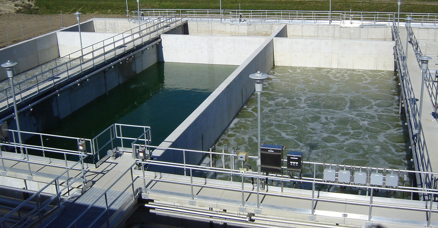
- SBR reactor tank(s) with inlet decant & internal baffles
- Fine bubble diffusers or coarse depending on OTR need; blowers (duty + standby) with air distribution manifold
- RAS / sludge return and sludge sump with pump
- Decanter / decant arrangement (submersible decant or dedicated decant weir)
- Polishing filters (PSF / Cartridge / UF optional) and disinfection (UV / NaOCl dosing)
- Sludge drying bed or mechanical dewatering (if required)
- PLC control panel with timer logic for SBR cycles, level sensors, DO sensors, flow meter
- Piping, valves, supports, civil works, installation & commissioning
Expected Performance & Uses
| Parameter | Typical Influent | Expected Effluent (SBR + Polishing) |
|---|---|---|
| BOD₅ | 200 – 400 mg/L | < 20 – 30 mg/L (good operation) |
| TSS | 150 – 350 mg/L | < 30 – 50 mg/L |
| COD | 600 – 1200 mg/L | < 150 – 300 mg/L (varies) |
| Turbidity | Varies | < 5 NTU (with polishing) |
| pH | 6.5 – 8.5 | 6.5 – 8.5 |
SBR is flexible for variable loads and intermittent operation; suitable for apartments, hostels, schools, hospitals, small industries. For high reuse quality (toilet flushing / cooling) add UF/RO and disinfection as needed.
Operation & Maintenance
- Daily: check inlet screens, pumps, blower status, DO & pH, cycle timers, decant function.
- Weekly: inspect diffusers, check sludge blanket in decanter, clean grit & O&G traps.
- Monthly: calibrate sensors, check blower belts/bearings, verify PLC timers & sequence.
- Periodic: sludge dewatering schedule, diffuser replacement if fouled, media inspection (if provided).
- Provide operator training, spares list and AMC options for stable performance.
FAQ — 30 KLD SBR STP
Q1: What is SBR and why use it?
SBR (Sequencing Batch Reactor) is a fill–react–settle–decant batch process in a single tank. Benefits: compact footprint, flexible operation, easy modification of cycle times for varying loads, and often lower sludge production.
Q2: How many cycles per day will this plant run?
With a 6-hour cycle and 20 operational hours, cycles/day ≈ 20 ÷ 6 ≈ 3.33 cycles/day. You can change cycle time as per site needs (shorter cycles => more frequent decanting).
Q3: What reports are required to finalise design?
Send raw influent lab report: BOD, COD, TSS, TDS, Turbidity, FOG, pH, temperature and any industrial contaminants. We also offer on-site jar tests and SDI/OTR tests.
Q4: Do you provide AMC & training?
Yes — we provide commissioning, start-up support, operator training and AMC packages nationwide.