300 KLD Sewage Treatment Plant — SBR & MBR Technology
Page Summary
This single page contains side-by-side technical & commercial information for both **300 KLD SBR** and **300 KLD MBR**. Default design basis: 20 operating hours/day, assumed influent BOD₅ = 250 mg/L. Final guarantees provided after site survey and raw influent lab report (BOD, COD, TSS, TDS, FOG, pH).
Applications: Apartments, Villas, Commercial complexes, Institutions, Industrial estates (Same as confirmed).
Common Front-End Process (Applies to SBR & MBR)
Disinfection method: SBR → Hypo (Sodium Hypochlorite), MBR → UV + Hypo (confirmed).
300 KLD — SBR (Sequencing Batch Reactor) Technical Details
Process Overview
SBR is a fill–react–settle–decant batch system that runs cycles (Fill → React (Aeration) → Settle → Decant → Idle). It gives excellent control over reaction time and settling and is flexible for variable loads.
Design Basis (SBR) — Digit-by-Digit
- Qday = 300 m³/day (300 KLD)
- Operating hours = 20 hr/day (default)
Qhr = 300 ÷ 20 = 15.000 m³/hr = 15,000 LPH.
Typical SBR cycle chosen = 6 hours (Fill 0.5 h, React 3.0 h, Settle 1.5 h, Decant 0.5 h, Idle 0.5 h).
Reactor Volume V = Qhr × cycle_time = 15.0 × 6 = 90.0 m³ (90,000 L). Include 15% freeboard → physical volume ≈ 103.5 m³.
Assume MLSS = 3,000 mg/L (3.0 kg/m³). Biomass mass = 3.0 × 90.0 = 270 kg.
BOD load/day = 300 × 250 ÷ 1000 = 75 kg/day.
O₂ req ≈ 75 × 1.4 = 105 kg O₂/day.
Conservative blower sizing (1.2 kg O₂/kW) → 105 ÷ 1.2 ≈ 87.5 kW → recommend multiple blowers totalling ~90–100 kW with VFD & redundancy.
With 6-hour cycle and 20 hr operation → cycles/day ≈ 20 ÷ 6 = 3.33 cycles/day. Decant fraction typically 30–40% of reactor → decant per cycle ~ 90 × 0.33 ≈ 29.7 m³; daily decant ≈ 29.7 × 3.33 ≈ 99 m³ (≈ 300 m³/day with rounding) — consistent with flow.
Sludge yield ~0.5 kg DS/kg BOD → DS/day ≈ 75 × 0.5 = 37.5 kg DS/day. At 3% cake → wet ~1,250 L/day.
SBR Equipment & Scope
- SBR reactor tank(s) with inlet, decant weir or submersible decanter, internal baffles
- Fine bubble diffusers & blowers (~90–100 kW distributed)
- Raw sewage pumps (duty+standby), decant pumps, RAS pumps
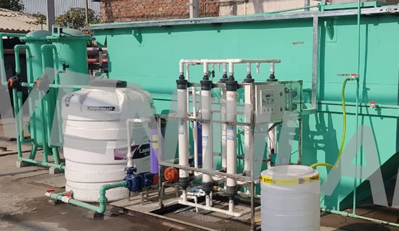
- Polishing filters (PSF / ACF / UF) & Hypo dosing skid for disinfection (SBR → Hypo)
- PLC panel for SBR cycle control, level sensors, DO sensor
- Sludge sump, thickener, dewatering (filter press / centrifuge / drying bed)
- Piping, valves, civil foundation & installation
SBR Advantages & Use Cases
Compact, good for variable/intermittent flows, easy to tune cycle times. Ideal for retrofits, apartment complexes and sites needing flexible operation.
300 KLD — MBR (Membrane Bioreactor) Technical Details
Process Overview
MBR couples biological treatment with membrane filtration (submerged membranes commonly). Eliminates need for large clarifiers, gives superior TSS removal and high-quality permeate suitable for reuse (with UV + Hypo). Best where footprint or effluent standards are tight.
Design Basis (MBR) — Digit-by-Digit
- Qday = 300 m³/day
- Operating hours = 20 hr/day → Qhr = 15.000 m³/hr → 15,000 LPH
Qhr = 300 ÷ 20 = 15.000 m³/hr (15,000 LPH).
Choose conservative design flux = 10 LMH (litres/m²·hr) for submerged membranes. Required membrane area A = 15,000 ÷ 10 = 1,500 m² total membrane area.
If modules have 10 m² active area → modules ≈ 150 modules (vendor dependent — final after vendor selection). This is a large area: confirm vendor flux & pilot performance.
Step 3 — Reactor volume & MLSSChoose HRT = 4 hours → V_bio = Q_hr × HRT = 15.0 × 4 = 60.0 m³ working volume (60,000 L).
MBR MLSS is high — assume MLSS = 8,000 mg/L (8.0 kg/m³). Biomass mass = 8.0 × 60.0 = 480 kg.
BOD load/day = 300 × 250 ÷ 1000 = 75 kg/day.
O₂ req ≈ 75 × 1.4 = 105 kg O₂/day.
Blower sizing with scouring: assume 1.2 kg O₂/kW then add 20% for scouring → blower_kW ≈ (105 ÷ 1.2) × 1.2 ≈ 105 kW practical total (split across multiple blowers, e.g., 4 × 30 kW).
MBR sludge yield lower (use 0.4 kg DS/kg BOD) → DS/day = 75 × 0.4 = 30 kg DS/day. At 3% cake → wet ≈ 30 ÷ 0.03 = 1,000 L/day.
MBR Equipment & Scope
- Screening, Grit & Oil-Grease trap
- Equalization tank & raw pump
- MBR tank with submerged membrane modules (total area ~1,500 m² assumed)
- Blowers for aeration & membrane scouring (total ~100–110 kW split)
- Permeate pumps, permeate headers, CIP connections for membrane cleaning
- Post-treatment: UV + Hypo dosing and polishing filters
- PLC with membrane control, TMP monitoring, DO control & remote telemetry
- Sludge sump & dewatering equipment (filter press / centrifuge)
MBR Advantages & Use Cases
Very high quality effluent (low TSS & turbidity), small footprint compared to clarifier-based systems, ideal for reuse (toilet flushing, cooling) and projects with strict discharge limits.
Tech Comparison Summary — SBR vs MBR (for 300 KLD)
| Parameter | SBR (300 KLD) | MBR (300 KLD) |
|---|---|---|
| Footprint | Moderate (clarifier included) | Smaller (no large clarifier; membrane area racks) |
| Effluent TSS | < 30–50 mg/L (with polishing) | < 5–10 mg/L (excellent) |
| Sludge | ~37.5 kg DS/day | ~30 kg DS/day |
| Power (approx.) | ~90–100 kW (blowers+pumps) | ~100–110 kW (blowers+pumps + scouring) |
| Capex | Lower | Higher (membranes & CIP) |
| Opex | Moderate | Higher (membrane maintenance & cleaning chemicals) |
| Use case | Flexible, good for batch/variable loads | Reuse-critical, strict discharge limits, space constrained |
Regulatory Compliance & Documentation
Both SBR and MBR designs will be engineered to meet TNPCB / CPCB discharge standards. Scope includes sampling ports, monitoring points, documentation support for consent & statutory approvals, and assistance with performance test certificates after commissioning.
Operation & Maintenance (Common Notes)
- Daily: check screens, pumps, air blowers, DO, pH and cycle logic (SBR) or TMP & flux (MBR).
- Weekly: clean screens & grit trap, check diffuser performance and ragging issues.
- Monthly: calibrate sensors, blower service, membrane CIP scheduling (MBR) and sludge management.
- Periodic: sludge dewatering & disposal, chemical top-ups for dosing & CIP, operator training.
- We offer AMC and remote monitoring packages for both SBR and MBR installations.
FAQ — 300 KLD SBR & MBR
Q1: Which technology is best for limited land?
MBR typically has smaller footprint due to elimination of secondary clarifier; choose MBR when land is constrained and higher effluent quality is required.
Q2: What data do you need to finalise design?
Raw influent lab report: BOD, COD, TSS, TDS, Turbidity, FOG, pH, temperature, and any industrial contaminants. Also site drawings & electrical availability.
Q3: What disinfection do you recommend?
SBR: Sodium Hypochlorite dosing is a reliable choice. MBR: UV + Hypo provides robust barrier — UV for pathogen inactivation + Hypo for residual if needed.
Q4: Do you provide warranty & AMC?
Yes — standard equipment warranty and customizable AMC packages for preventive maintenance, spare parts and operator support.