50 KLD Sewage Treatment Plant — MBBR (Moving Bed Biofilm Reactor)
Page Summary
This page gives a full technical package for a 50 KLD MBBR using standard design basis: 20 operating hours/day, influent BOD₅ = 250 mg/L (assumed). All calculations show digit-by-digit arithmetic. Final design and guarantees provided after site survey & raw influent lab report.
Process Flow (text)
Design Basis & Digit-by-Digit Calculations
- Plant capacity Qday = 50 m³/day (50 KLD)
- Operating hours = 20 hr/day (default)
- Influent BOD₅ assumed = 250 mg/L
- MBBR HRT (aeration zone) = 4 hours (typical)
- Carrier media fill fraction = 50% (typical 40–60%)
- MLSS (mixed suspended solids) lower importance in MBBR; biofilm attached to carriers is principal biomass
- O₂ requirement factor = 1.4 kg O₂/kg BOD
Step 1 — Hourly flow
Convert to litres per hour: 2.5 × 1000 = 2,500 LPH.
Step 2 — BOD load
Step 3 — Aeration (reactor) volume
Working volume V = Qhr × HRT = 2.5 × 4 = 10.0 m³ (10,000 L).
Add 15% freeboard → physical reactor volume ≈ 10.0 × 1.15 = 11.5 m³.
Step 4 — Carrier media volume
Media provides large specific surface area (typical 400–800 m²/m³ depending on type) — verify with vendor.
Step 5 — Oxygen requirement & blower sizing
Assume 1.2 kg O₂ per kW (practical) → blower_kW ≈ 17.5 ÷ 1.2 = 14.583 kW. Recommend 15 kW total blower power, split (e.g., 2 × 7.5 kW blowers) with VFD & fine-bubble diffusers for efficient oxygen transfer.
Step 6 — Clarifier sizing (post-MBBR)
Circular clarifier diameter d ≈ √(4A/π) = √(6.6668/π) ≈ 1.456 m → choose practical diameter ≈ 1.5 m. Provide hopper and RAS capacity design though RAS is lower in MBBR (main biomass is attached to carriers); provide sludge return and wasting arrangement from sludge sump.
Step 7 — Sludge estimate
At 3% cake solids → wet sludge ≈ 5.0 ÷ 0.03 = 166.7 L/day.
MBBR Technology — Details & Carrier Media
How MBBR works: Floating carriers provide protected surface area for biofilm growth. Media kept in suspension by aeration; pollutants are consumed by biofilm while suspended solids are low. MBBR is robust to shock loads and easy to retrofit into existing tanks.
Carrier selection & specifics
- Common carriers: Kaldnes K1, K3, AnoxKaldnes — HDPE, specific surface area 400–800 m²/m³.
- Media fill fraction commonly 40–60% (we used 50%).
- Provide sieving/mesh screens at outlet to prevent media washout; design media retention pockets for maintenance.
- Choose carrier type after pilot or jar tests; media durability & cost considered.
Operational notes
- Fine-bubble diffusers recommended for good oxygen transfer and mixing.
- Maintain DO > 2 mg/L in aeration zone; monitor biofilm growth and control wasting.
- Periodic media cleaning (if heavy fouling/scaling) and replacement lifecycle planning.
- Retrofit option: use existing aeration tanks — drop-in carriers reduce civil scope.
Scope of Supply & Main Equipment
- Bar screen, grit trap & oil & grease trap
- Collection / Equalization tank with mixer
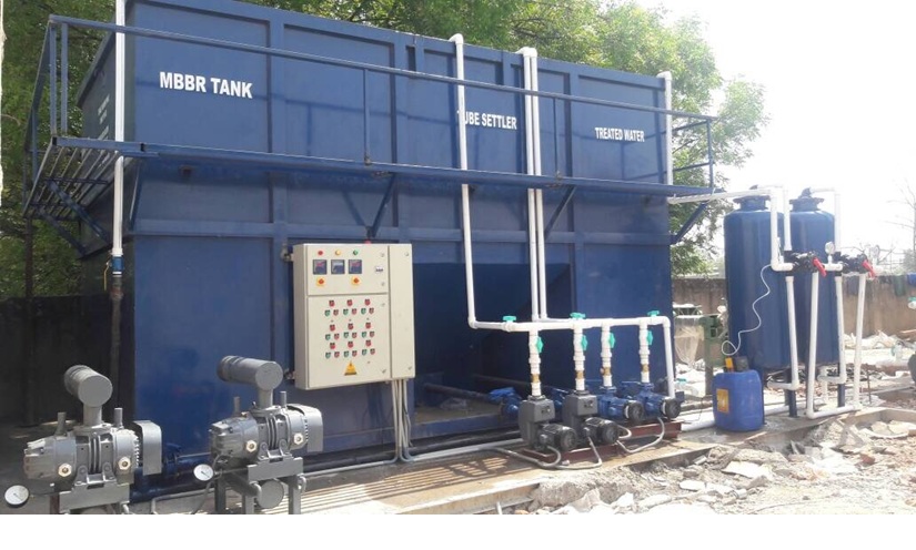
- MBBR aeration reactor (10.0 m³ working / 11.5 m³ physical) with carrier media (≈ 5.0 m³)
- Fine-bubble diffusers & blowers (total ~15 kW split)
- Secondary clarifier (Ø ~1.5 m) with hopper & sludge sump
- Polishing (PSF + ACF + Cartridge / UF) and disinfection (Hypo / UV)
- PLC control panel, DO & level sensors, flow meters, pressure gauges
- Sampling points, media retention screens, access manholes & service platforms
- Piping, valves (UPVC/HDPE/SS), civil works, installation & commissioning
Material of Construction (MOC) & Installation Notes
- Reactor tanks: RCC / MSEP / FRP with rubber lining depending on site and budget
- Diffuser piping: HDPE/UPVC; headers & certain wet parts: SS304 as needed
- Carriers: HDPE with proven vendor supply; provide retention screens to prevent escape
- Blowers on skid with silencer; provide VFD for DO control and energy savings
- Ensure electrical supply capacity ~kW for blowers + pumps + controls (detailed sizing on site)
Expected Performance & Typical Applications
With correct design and polishing: BOD & TSS typically reduced to < 30 mg/L; turbidity reduced with PSF/UF. MBBR is suitable for apartment complexes, institutions, hotels, hospitals, and light industrial estates needing compact, reliable STP with low operator attention.
| Parameter | Typical Influent | Expected Effluent (MBBR + Polishing) |
|---|---|---|
| BOD₅ | 200–400 mg/L | < 30 mg/L |
| TSS | 150–350 mg/L | < 30–50 mg/L |
| Turbidity | Varies | < 5 NTU (with PSF/UF) |
Operation & Maintenance
- Daily: Check inlet screens, pumps, blower run status, DO (> 2 mg/L), reactor mixing and outlet clarity
- Weekly: Inspect carriers (visual via sampling port), check for media fouling, clean inlet screens
- Monthly: Calibrate DO & level sensors, inspect diffusers & clean if needed, check blower filters
- Periodic: Replace worn diffusers, top-up/replace small fraction of carriers if damaged, sludge dewatering & disposal
- We provide operator training, commissioning tests and optional AMC packages for continuous performance
Common Issues & Troubleshooting
- Low DO / poor treatment: Check blowers, diffuser clogging, and DO setpoints — increase aeration or check mixing.
- Excessive suspended solids: Check carrier wear (friction), perform outlet screening and improve clarifier performance or add UF polishing.
- Carrier loss: Inspect outlet media retention screens and piping; repair worn screens.
- Foaming: Dose anti-foam and check surfactant sources in influent (pre-treatment with equalization helps).
FAQ — 50 KLD MBBR
Q: What data do you need to finalise the design?
We need raw influent lab report: BOD, COD, TSS, TDS, FOG, pH, temperature, and any industrial contaminants. Also site levels and power availability.
Q: How often should carriers be inspected or replaced?
Visual inspection monthly is recommended; carrier life typically many years (5–10) depending on abrasion & chemicals. Replace only damaged carriers as needed.
Q: Can MBBR be retrofitted into existing tanks?
Yes — MBBR is excellent for retrofit: add carriers to existing aeration tanks with minimal civil work and upgrade aeration/blowers as needed.