20,000 LPH Industrial RO Plant — RO + UF Pretreatment
Overview
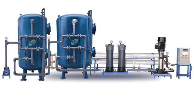
This 20,000 LPH (20 m³/hr) Industrial RO Plant is designed for continuous industrial duty — packaged skid with multiple RO trains, UF pre-treatment for turbidity & colloid removal (recommended for STP/ETP polishing or surface water), anti-scalant dosing, CIP, and instrumentation for automated operation. Development follows TNPCB/CPCB compliance where discharge/reuse required.
Process Flow (UF → RO → Post)
UF placed after ACF removes turbidity & colloids, dramatically improving SDI and protecting RO membranes — essential for industrial feed with variable feedwater quality.
Design Basis & Digit-by-Digit Calculations
- Permeate (required) P = 20,000 LPH = 20,000 litres/hour
- Convert to m³/hr: 20,000 ÷ 1000 = 20.000 m³/hr
- Design recovery R (single-pass typical) = 70% (adjust after feed analysis)
Feed & Reject (step-by-step)
Qr = Qf − P = 28.571428571428573 − 20.000 = 8.571428571428573 m³/hr → 8.571 m³/hr reject (~8,571 LPH).
In litres/hour: Feed ≈ 28,572 LPH; Permeate = 20,000 LPH; Reject ≈ 8,571 LPH.
Membrane Area & Element Count (worked example)
Required membrane area A = Permeate (L/hr) ÷ Flux (L/m²·hr) = 20,000 ÷ 16 = 1,250.0 m².
Typical 8" element active area ≈ 6.0 m² → elements = 1250 ÷ 6.0 = 208.333... → round up to 209 elements.
Example train layout: 13 vessels × 16 elements (208) + 1 spare element or 8 vessels × 26 elements depending on vendor vessels. Split into multiple trains for CIP flexibility (e.g., 4 trains × 52–53 elements).
High-Pressure Pump Power Estimate
Design pressure = 15 bar → Head H = 15 × 10.197 = 152.955 m.
Hydraulic power (W) = ρ × g × Q × H ≈ 1000 × 9.81 × 0.007936507936507936 × 152.955 ≈ 14,862.2 W ≈ 14.862 kW.
Assume overall efficiency η = 70% (0.70) → Installed motor = 14.862 ÷ 0.70 ≈ 21.232 kW → round to practical rating 22–25 kW per pump depending on head losses & piping. Use duty + standby pumps and VFDs.
Note: Final pump selection must include piping losses, filter differential, valve & membrane pressure drop, and temperature corrections.
Membranes, Skid & CIP
| Item | Specification / Note |
|---|---|
| Membrane Type | Polyamide TFC brackish / industrial grade (DOW / Toray / LG options) |
| Design Flux | 12–18 LMH (we used 16 LMH) |
| Elements (indicative) | ~209 elements (final vendor to confirm) |
| Skid | SS316 / SS304 frame; pressure vessels; instrumentation; CIP manifold |
| CIP | Acid & alkali dosing pumps, CIP tank & automatic valves for train-level CIP |
Recommend dividing membranes into multiple trains for staged CIP and redundancy (e.g., 3–4 trains). Include membrane spare inventory (10%).
Pre-treatment (UF + PSF + ACF + Cartridges)
- Coarse Strainer / Bar Screen — protect PSF from debris.
- PSF (Multimedia Filter) — turbidity & suspended solids removal sized for feed Qf.
- Activated Carbon Filter (ACF) — remove free chlorine and organics to protect RO membrane.
- Ultrafiltration (UF) — recommended for turbid or variable feed; reduces SDI and ensures stable RO operation.
- Cartridge Filters (5 μm → 1 μm) — final particulate protection before HP pump.
- Anti-scalant & pH dosing — protect membranes from scaling species.
UF sizing: choose modules & flux based on required permeate; for 28.6 m³/hr feed into RO, size UF feed to provide stable low-turbidity feed (typical UF recovery 85–95%).
Expected Performance & Reuse
| Parameter | Feed (typical) | Permeate (expected) |
|---|---|---|
| TDS | 500 – 5000 mg/L (site dependent) | Depends on membrane rejection (90–99%). Example: feed 3000 mg/L → permeate 30–300 mg/L (single-pass) |
| Permeate Flow | — | 20,000 LPH (design) |
| SDI | Varies | < 3 (with UF) |
| Use | Industrial process, boiler feed (after polish), cooling tower make-up, or further polishing for drinking depending on treatment) | Reuse / distribution as per application |
For ultra-low TDS targets (<10 mg/L) consider double-pass RO + EDI or polishing stages; for ZLD objectives integrate evaporators / crystallizers for concentrate handling.
Operation & Maintenance
- Monitor feed & permeate TDS, flows, differential pressures, and TMP; schedule CIP to maintain flux.
- Keep anti-scalant, acid & alkali stocks for CIP and dosing.
- Two pumps per duty (duty + standby) recommended; VFDs for energy savings & soft start.
- Spare membrane elements 10–15% recommended onsite for quick replacement.
- Provide local operator training & annual preventive maintenance (AMC).
FAQ — 20,000 LPH Industrial RO Plant
Q1: What is the lead time for supply?
Typical supply lead time: 6–10 weeks for standard skid; 10–14 weeks for customised heavy-duty skids depending on membrane availability and civil schedule.
Q2: What test reports do you need?
Send raw water TDS, temperature, turbidity, hardness, iron, silica, SDI (if available). We provide jar tests and SDI tests on site if required.
Q3: What recovery can be guaranteed?
Recovery depends on feed water chemistry. Typical single-pass recovery 60–75%. For higher recovery or ZLD routing, additional stages or evaporators required.
Q4: Do you support ZLD / concentrate handling?
Yes — we can integrate RO with evaporators / mechanical vapor recompression systems for ZLD projects. Separate quotation required.